Thursday, 11 April 2013

ECC83 Valve with a low voltage 5V A/C heater (12AX7 Tube)

So why run an ECC83 / 12AX7 with a low heater voltage and what happens when you do?

I have a transformer from an old Linear Diatonic cage amplifier. How old? Well the 32uF+32uF can capacitor has May '58 as the date, but they didn't have just-in-time delivery in those days so I would put it at very early 60's best case. It was originally a two ECC83 + EL84 output with an EZ80 rectifier. It also had an auxiliary 6.3V and HT (B+) socket on the back, so I knew it had some capacity left over. It got put into a guitar amp and became three ECC83 + EL84 output +EZ81 rectifier. (I know, EZ81 is a 6.3V version of EZ80, but I had a new one and it worked OK.)

Now I want FOUR (new preamp + FX loop) ECC83 + EL84, but this may be pushing it a bit, and the last thing I want to do is slowly cook the transformer. If I lose the rectifier valve and go for a semiconductor bridge with a zener to drop the voltage back then I could possibly run the additional valve from the now unloaded 5V heater winding and reduce the total load on the transformer. The light heater loading of ~0.3A should allow the voltage to rise above 5V or safeguard from a low mains supply, but after looking on the net I could find very little in HARD figures. Most advice I saw was that this possibly won't work, with one reliable source saying yes it will be OK. (Valve Wizard)

The only way to decide was to go measure the configuration I was going to use. The measurement below used a DC lab supply for the heater. The voltage supply I have is limited to 210V so I couldn't test with a higher value. The valve was a JJ-Tesla ECC83S with about 50 hours on the clock. I would be looking at the 1-2-3 connected part of the triode. The other half was not connected and the heater was between pins 4 and 9 only. In test this would mean that the valve would be colder than if both heaters were working, but I think of it as margin.

 
Test Circuit. R3 is selectable as 120k or 240k
Firstly I did some DC testing to bottom out the heater. The heater cold resistance excluding wiring but including the socket was 6.156 Ohm. With a 6.3V supply and ignoring wiring this would draw 1.02A at switch on. In reality this would possibly be lower, but a good (6 Watt) kick to the guts none the less when turned on. When working at 6.3V the single heater draws 155mA equating to a hot resistance of 40.6 Ohm and a dissipation of 0.98 Watt. Working at 5V it drew 136mA  giving an effective hot resistance of 36.76 Ohm with a dissipation of 0.68 Watt which is 70% of the dissipation at 6.3V

With a 1V pk-pk test signal applied to the test circuit I got an output swing of 54.1V pk-pk with an anode resistance (R3) of 120k. With R3 = 240k the swing was 60.2V which is pretty much on the money.  Spice simulation came out as 55.16V  for 120K and 65.5V for 240K, so close enough.

Putting a 4V pk-pk input swing on the input it would drive the output into saturation. This should highlight any obvious weakness in using 5V. Firstly I looked at the negative side as this represents the largest current through the valve.
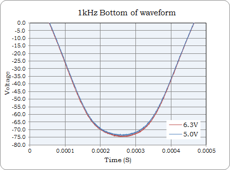
6.3V vs 5V. Input = 4V pk-pk input 210V supply voltage.

 There is no huge difference to be seen between either heater voltage, the 5V heater gain (blue) looks just shy. The top of the waveform should be well saturated so we will check that next.

As above....

The 5V heater is again a little shy of the 6.3V setting, but the behaviour entering and exiting saturation is pretty much the same. When lowering the input swing and operating in the available linear area the 5V gain is slightly lower but otherwise perfectly useable. Even at a 4V heater voltage the valve is still working in a healthy manner. With a 3V heater voltage the gain has dropped, but this is just experimental data.


So what conclusions does this present. For me and the new guitar amplifier, I'll happily put the first valve with both heaters on the 5V supply. Both stages are below maximum gain anyway. Some voices on the net did say I'll ruin the valve this way, but I found a table in an old design book which showed extended life extending to thousands of hours so I am happy with that.  I will also consider putting a series resistor in all the 6.3V supplied preamp valves from pin 9 to the centre pin of the base and then to the heater wiring. A 2.2 Ohm resistor should reduce the switch on current in the heater from 1 Amp to ~600mA whilst dropping the working voltage to ~5.68V (0.615V drop or ~82% of full heater dissipation) This should have virtually no effect. If it does, then 1 Ohm should be fine.

On the other side of the coin. I should possibly see if I can get a more representative voltage for the supply, 210V is sort of low.

EDIT / UPDATE 1

Below is with a 270V power supply with 6.3V and 5V heaters compared. This last test had both heaters wired in circuit. No change from previously observed measurements including at full saturation.

240K and 1.2V input. 73V pk-pk swing.

EDIT / UPDATE FINAL

I have an _OLD_ Mullard Ecc83/12AX7, silvering gone spotty really is shot. God knows how many hours. It still has some output but very non-linear. It normally sits on my desk as an ornament. In the 270V HT / B+ test it performed equaly badly with 6.3V and 5V heater voltages. The 6.3V specification seems to have a lot of margin built in. Just remember to include mains supply tollerance etc. when looking at your own transformer!


Friday, 5 April 2013

DIY Front Panel in Acrylic / Plexi

New amp needs a new face. Looking around in the UK I can get a custom front panel made, but it seems a lot more costly than you can get say in the U.S. Some want .DXF as the file and not having Autocad or a package with this format blocks that route. What I could source very cheaply was some cut to size 1.5mm thick clear acrylic and a couple of sheets of water slide decal paper for a laser copier.

The acrylic was delivered promptly as four sheets cut to size and a set of panel graphics produced using Paint Shop Pro 9. The images were then all mirrored as the plan is to place them on the back of the acrylic and view them form the other side, ie the front. I can then paint over the transfer effectivly sealing them in. The paint observed from the front would have a perfect  finish no matter how lumpy it was put on, or that's the idea anyway. A few old CD cases proved that using finger daubed water acrylic paint.

The laser copier paper arrived with a warning about possibly melting onto the fuser roller of the copier which was not in the advert selling the paper (ebay). However the bigger the copier the more ECO friendly it is and the large business types therefore have a lower than normal working temperature. There was no issue with the printing and it gave razor sharp results. Unlike inkjet water decal paper it needs no lacquer overcoat which is why I chose it this time.

To make the panel it was first taped in place to the front of the chassis. Using an indelible marker the position of the controls was marked onto the back of the acrylic using the holes in the chassis as a guide.  On an earlier attempt I used a scribe which leaves a finer line, but the unevenness made ripples in the transfer on application.

Finished Item...Chuffed to bits!

Test acrylic taped in place and marked.

The transfers we cut out close and then placed in position. The best method I found was to use a white paper sheet under the acrylic with straight lines printed / drawn on. This way you have a datum for the bottom edge of the acrylic and the lines assist in ensuring that the top of the transfer where the wording is is straight.  It took a while to get the result right but here is what I found best.

Lined paper assists getting it straight.

Soak the transfer for thirty seconds and then place to one side for another. Line the acrylic up on the guide paper and place a bit of water where you want the transfer to go. Without this dab of water the positioning time is about twenty seconds. what can then happen is that part of the transfer can grab and when you attempt to move it the transfer will stretch or distort. The bit of water underneath gives you minutes of working time, however at this point it is prone to handling errors if you try to place another transfer as it is effectivly floating.

Using a ruler place as close as possible, note printed mirrored!

After positioning the transfer I would then flip the panel over. The transfer is now against the guide paper. It has enough friction with the guide paper that you can still finely position it if needed by moving the panel. When it is all correctly positioned simply apply pressure, the excess water will be pressed out and the transfer will adhere to the front enough to resist handling. The transfer can still be lifted with a knife edge if required. Having lined paper to do this part also helps but missing in the shot below.

Fliping over to check position and then press to affix.


With the transfers in place I painted the rear of the panel with several coats of artists acrylic paint. I could easily use a spray paint, but the acrylic allows me to test and wipe off. After several coats I did a final coat painted some paper and placed this as a protective backing.

Final coat and backing paper will form a protective seal.

The final result, well really please with this. The edges of the acrylic had some small chipping under the green protective film, but a quick sanding will remove these and they will sit behind the cabinet woodwork anyway.

With painting the transfer blends perfectly to the panel.


It worked out cheaper than having a custom panel, and I still have acrylic and transfers for the rear and a spare front.  One other point about the acrylic paint. It is not fully opaque to light. If I cut a small hole in the backing paper but not through the paint I could shine light  from behind which you would see as a bright yellow glow from the front.. I may not go for a panel mounted power light, but insted use a 3mm white LED mounted behing the panel to illuminate a small circle of blank panel adjacent to the power switch to indicate that the amp is on.

As a final note, If you are thinking if edge illuminating the panel then the transfer edge will become visible.

Wednesday, 3 April 2013

Resistors, Carbon Comp vs Metal Film in Valve / Tube Amp Design.

As in previous post, I don't suffer snake oil etc in circuit design. _However_ whilst shopping for some parts I noticed I could also buy brown carbon composite resistors with nostalgic 3+1 coloured rings for 30 pence. Now they have lots of  know issues but I remembered reading years ago about voltage coefficient in my copy of Horowitz and Hill Sec.Ed.  The question I am looking at is could the voltage coefficient alter the sound of the amplifier? According to H/Hill above 250V the resistor changes value and at 1kV it is out by 29% (Chapter 6, pages 372/3). We are dealing with lower voltages, but across the anode resistor at clipping it could see ~250V potential, so I would like to check that area.

I happened to find an old carbon comp resistor, 680k value hidden away. With carbon composition this  is more of a pre-soldered guide than an absolute value. It was more like 688k.  I decided to do some DC tests to see how much, if any, it would change over a 210V range against a metal film of the same value.

Percentage change with applied voltage.

In the above plot there is a clear change in apparent resistance of the carbon resistor against an applied DC voltage. The measurement contradicts a H/Hill statement that it is really only above 250V where the voltage coefficient becomes apparent. Maybe they meant significant. To put this in prospective, of the original 688k value it represents a drop in resistance of over 20k. The metal film (red plot) is stable at 100.0%.

Having repeated the test and confirmed the behaviour I needed to know if this was something that takes seconds to change or is this change instantaneous and works in real time.

To check this I constructed a potential divider out of two resistors. The bottom resistor was a 62K metal film and the measurement was made across this device. The top resistor was the device under test being either the 688k carbon composition or a 680K metal film resistor. Using a linear ramp source to 210V I could measure the lower reference resistor and determine the behaviour of the top resistor. The tail off at high voltage is the probe capacitance, so linear to +170V.

Real Time Voltage vs Resistance change.

In the above plot the carbon (red) is plotted against the metal film (blue) with the left hand scale. You can see that the red line drops slightly more voltage at the 0.0001s (0.1ms) point as it has a slightly higher resistance value. However as the voltage rises it crosses the blue plot and ends up with a lower voltage drop. This is real time compression well within the audio range.  To clarify the difference in voltage drop is plotted in green on the right hand scale, -7V to +3V. This shows that at the 0.1ms point the carbon resistor is dropping about 1.3V more than the metal film as to be expected being a higher value resistor. However with ~180V applied at 0.48ms the carbon film resistor is now dropping 4.8V LESS. It has shrunk in real time.

Piecewise Linear and Poly Curve Fit.

In a final look at the data you can either view the drop in resistance as a three section piecewise linear (blue, orange & purple lines) with three gradients or curve fit to the equation shown in the title.

The real world effect for valve / tube amplifier designers is that the carbon composition resistor can add some non linearity and compression not normally present in metal film. In my opinion it would be a mistake to consider the use of carbon in the early stages of a cascaded design. When taking the first measurement at DC the digital display would flick around on the carbon resistor but was rock steady with the same value metal film. The noise is really something else. However as an anode resistor in the overdriven /clipping stage, well it may be worth the 30p to someone. I however will probably stick to metal film based on reliability. Is the above effect audible? I will have to say-

 possibly.

Tuesday, 18 December 2012

Technofret Under String Fret Level.

I bought a "Technofret Advance Fret Levelling System" (or TAFLS) from their UK ebay site. It costs £37 including postage (as of today $60 USD). As you can imagine the title "TAFLS" is more than the sum of parts, or sum (cash) of materials. What I got for my money is a single length of  1.6mm aluminium U section channel 480mm long. A straight edge, 5mm thick and about 450mm long. Also included were 3 blocks of Aluminium bar and two grades of abrasive on double sided tape. So far it doesn't sound like I got a good deal for the cash. No instructions or guide were included, but the idea of under string fret dressing seemed whole enough to splash the cash. The real cost is possibly the flatness of the edge and each side of the channel, which are flat against each other and against an optical grade flat at work. It's flat.


Technofret Advanced Fret Levelling System & My String Lifter.


 The idea is simple and an appealing one. The fretboard under tension (allegedly as I don't have information proving this) doesn't bow in a pure curve. With the stings on and the neck under truss rod tension the neck _can_ form a slight S type bend. Using the TAFLS you can level the frets with the board flat under tension which will also (possibly) include any unwanted bows.  The truss rod is then released slightly to set the correct relief and you should end up with a better relief curve. Or so it says on the tin, or didn't in this case.

First part of the process is to get the marker pen out and blacken the tops of all the frets. Usually I do this after I have taped up the fretboard but ideally the blocks used n the levelling process need to rest on the wood so you have to do this with the board unprotected. I managed to get two indelible marks on the fretboard. Doh!

With the strings set to normal tuning flatten the fretboard by tensioning the truss-rod. To check straightness you use the three supplied blocks, one at the first fret, one at about the 17th fret and then somewhere in the middle should do. I  used a small LED torch to gauge the gap. By slowly adding tension on the truss rod you can get to the point that you have no light between the straight edge and the middle block. By moving the straight edge left to right you can also check at what point it can begin to drag on the middle block. One issue is that the straight edge is about 38mm tall and is balanced on its 5mm width on the two outermost blocks. Moving the truss rod will at some point cause the edge to fall and clatter off onto the fretboard if you are not careful. It complicates the set-up but not much.I did check the tuning after moving the truss rod but in my case it hardly changed.

Checking relief at middle block.
 
Next get the U channel out. It came with two grits of 400 and 600. As I am not in a rush I used only the 600 grit and then used my own tape to place a 1000 grit strip on the other side of the channel. The channel being 1.6mm thick didn't readily fit under the strings at the first fret frets, so I had to lift the strings. The advice from  TAFLS is to use a spacer to lift the strings up, checking correct tune. However I had a small L-shaped bit of alloy handy which I cut to run under two strings at a time. With some protective tape underneath I could easily lift two strings a fraction.

DIY String Lifter

With the frets marked up I did a gentle pass with the 1000 grit. I had already done a traditional fret dress with a 350mm plane as a flat with the strings off, so I was interested to see if the TAFLS idea held up. As you can see below frets 1-4 are being abraded whilst fret 5 (visible) 6, 7 and 8 have a dip and the black marker is still there. Strat necks are more likely to show this behaviour apparently though I have no real solid information myself. This didn't surprise me as the guitar did fret out on the first few frets if the action was set too low.

Fret five, still black


 I would step across the neck one string at a time from low E to high E doing a small circular motion each time and then turn the U channel round and repeat the process from high E to low E. I would always lift the strings in pairs to make room for the U channel flange. After getting down to all frets showing abrasion I turned the channel over and used the 1000 grit to complete the initial dress.


After completing the dress the fret ends were re filed and the crowns re profiled. The frets were polished to 2500 grit and then a Dremel and some metal polish to finish off.


 At the end of the process I can say  that the TAFLS worked a treat on this neck. This said, a 7.5inch neck will never be as low as my other guitars with a more forgiving  radius I can say that this time it was better than before and the action is now as low as I can hope for allowing bends not to fret out. Possible I didn't flatten the fretboard in my previous attempt but despite feeling it was expensive for what I got, the result made it money well spent.I do worry that the channel doesn't feel robust so I have a separate place to store it. Just for the record, I don't have any association with the source of the TAFLS other than I purchased one for full price. There are other questions I would like answered. How much does adding tension to the truss rod change the neck, should it be a combination of added tension and slightly de-tuning the strings? Where is it best to place the middle block and in the case of large block inlays, is it OK to use fret 8 where there is no inlay? It isn't the only under-fret, under tension method available, but it was local and not too expensive. Maybe it's a fashion that will soon disappear, but I can see the logic of dressing frets with the neck under tension.


Friday, 21 September 2012

A New Valve / Tube Tilt Tone Control.

This is very much an experiment at the moment. Years ago QUAD brought to a wide audience a very handy tone control for their HiFi preamps It was termed a Tilt control but is also known as a contour control which I find less descriptive. It differs in being a shelved filter so you control a broad range of frequency by a bit rather then a small area by a lot. It is better at changing the emphasis of the tone and not the tonal character. The idea is appealing but it is normally wrapped around an op-amp. I could passively add it but I came up with a topology which was far more tempting.

The topology places the control within the phase splitter and the output stage in my EL84 amplifier. The output is fed back into one side of the phase splitter. I liked the idea as the circuit has a nice symmetry which appeals.  The complication is it sits within the feedback loop from the speaker to the phase splitter so it's was always going to be a bit of a battle to ensure stability. If you look at the schematic below you can see that it would be very easy to add to an existing amplifier as it sits on top rather than within a normal EL84 output stage. The other issue I have found is that the switching from Pentode to Triode it changes the feedback gain and hence gain of the tone control.Click on the schematic to see it full size.


The frequency plot below is a multi-run simulation where the  TILT control is moved from 0k to 470k in linear steps. It shows clearly how at one end of travel it has bass boost and treble cut and at the other bass cut and treble boost.

In the circuit R47 (33K) sets the amplitude of the boost and cut in conjunction with R48 the feedback resistor. Current work is refining the balance between the two values which results in a good degree of tone control without sacrificing stability. It has proven to work well as a tone control but it would be better if the existing bass-mid-treble was not directly prior to this stage in my test amp. Better would be a topology closer to a trainwreck circuit where the tone control is early in the preamp cascade. That way you could alter the tonal emphasis going through the distortion stage and correct in the power stage.

If you are content with a boost / cut of a few db then phase shift can be kept very low, something that HiFi designers may find useful, which brings this full circle. It is trivial to obtain flat response at the bass end to low Hz.

EDIT. Looking at the above simulation the overall gain is ~29dB with flat gain, it should be nearer 18dB. I guess I took my eye off the gain whilst optomising tilt. The omission was to leave the grid capacitor C14 not tied into the feedback point. I'll address this excess gain and see if the instability issues previously noted disappear.

Friday, 27 July 2012

Update on Routing Out a Guitar Body.

I thought that I'll drop in a quick update on the earlier post (May 2012) on routing out a guitar body. This is just a quick picture of the finished guitar. Works fine but cheap pots and pickups are going to be dumped and replaced with something better. At least I got the bridge in the right place and the neck angle correct. There is an odd wavy reflection above the neck pickup, but this is just the reflection. It does show the arm-rest angle and the curve of the horns etc. The truss rod cover is bookmatched in case you are looking for one. Overall, very happy with how it turned out. The bridge pickup is tapped with a 47nF shunt capacitor accross the slug coil. Pickup bobbins and thin copper wire have arrived so I'll be winding new pickups after the summer break.


Monday, 16 July 2012

Build A Guitar Humbucker Pickup Frequency Response Analyser For Peanuts

The Shuntbucker frequency plots obtained in my earlier post were originally obtained using an Agilent arbitrary frequency generator and buffer amplifier as the source and the output amplitude recorded on an LeCroy 1GHz digitising scope. I am lucky in that I have access to some neat equipment, but most people won't.  In this post I'll outline how anyone with around £15 can do the same measurements and add thoughts on how to do full dynamic impedance measurements on pickups. I hope to try rewinding some pickups soon. The rational here is when winding pickups how do you know where you are going if you don't know which way you came from.

The first part is how to get a signal into the pickup in a way that is reasonably representative of a string above the pole pieces and is frequency agnostic. The issue is more complicated with humbucker pickups as they have two coils which produce an opposite signal to an open field magnetic source.  It will need some sort of magnetic injection which, with a bit of luck you can obtain for free. You will need to source an old computer hard disc drive and some star-point type screwdrivers. Open the drive, release the magnet assembly in the corner and extract the pickup head assembly as seen in the bottom left hand corner below. The bearing has a small screw on the side which will either need the correct screwdriver to remove or a pair of pliers and just grab the screw head and turn.


Once removed ditch the bearing, its magnetic so you will want it out of the equation. The pickup arm assembly can be removed with a junior hacksaw, its just the voice-coil that we are after. There may be a parking magnet as part of the voice coil, if so snap it off. When finished you should have something like this, well after soldering a lead on anyway. There will be some drive circuitry on a flex PCB mounted on the arm, It will provide a good connection point to solder to the coil, just remember to cut any tracks leading to the drive chip from the coil with a craft knife.


The coil should have a DC resistance of about 10 to 15 ohms, high enough to drive with a domestic amplifier. However my test kit has a 50ohm output impedance so I had to knock up a buffer amplifier. It is based on a OPA548F high power op-amp. Its data sheet shows a relevant schematic. To drive a volt pk-pk maximum into the coil will only require an amplifier with under a 1/2 watt capable drive. I'll come back to drive later as you don't have to make this part.


The reason this coil is ideal is that I can mount it centrally and orthogonally to produce a good response by working both coils at the same time.  It will produce an opposite polarity field into each coil thus producing a combined in-phase signal which is what I want and what a string does. The coil construction means that the self resonance will be decades above the coil under test ensuring good measurement. Below was an earlier attempt with a slightly different coil. I used Blu-Tack to hold it firmly in place. It runs exactly in line with the split between the two coils. In this configuration a symmetrical in-phase output will be produced, as you would expect by plucking a string. If I lift the coil and hold it horizontally above the pickup It will produce a matched out-of-phase signal which will combine and cancel as you would expect from an external field into a humbucker. Moving the coil away from this position say to the side changes the output balance and phase of the coils. This would produce cancellations when attempting to measure the frequency response. 


The output of this was fed to a board with resistors and capacitors representing the volume and tone circuit of the guitar and the 1Meg input impedance of my amp. I used a 10Meg input impedance scope probe so not to load the circuit.  The coil idea proved to work very well and produced repeatable results even after disassembly and reassembly. However most people can't afford a scope, signal generator and probes, and my issue is that I can only have limited access to them at work. However I have a potential solution which although I have not yet tried _should_ work for anyone  wishing to measure pickup response. (See EDIT below)

Visual Analyser 2011 XE (VA) from sillanumsoft.org is a free download unlimited real-time software scope, spectrum analyser and lab tool-kit. It uses a PC sound card to provide a real-world interface. The coil should be high enough impedance to be driven from a good headphone output. If your card does not have enough drive try lowering the output or wiring the left and right output together. You can also buffer with a HiFi amplifier on a very low setting. For the input you will need to wire a high impedance buffer between the Humbucker coil and the line input. Any high impedance audio op-amp buffer circuit should suffice. Generally the input impedance of a soundcard is quite low when compared with a guitar amplifier input stage. Most valve amplifiers have a 1 Meg input. The scope function will measure the output amplitude provided by the pickup when driven with the VA software signal generator.  With this configuration your total kit outlay will be the cost of a broken hard drive and building a buffer amplifier. If appreciative please consider a Paypal donation to the software engineer who wrote Visual Analyser. I have no ties to the author of VA who I believe is from Italy.  The software was used in the analysis of the triode / pentode switch mod harmonic test in an earlier post.

EDIT: I have now ran a quick test using VA and a normal Dell computer with an on board sound card. I placed a 470K resistor in series with the line in jack to prevent the pickup getting loaded by the low line in impedance. I used the left and right headphone output combined to drive the HDD coil. The sweep was set to 24 points an octave and the spectrum analyser set to peak hold. The waveform generator was set to sweep from 80Hz to 20kHz. I left it to run for a while to build up the plot below. The cursor measurement shows the peak at 5.758kHz. You can also notice that from 2.5kHz the amplitude rate of change increases towards the resonance peak.  It will look different from my previous plot as it records in dB and not straight mV. (Click on the plot to see full size)


On the Sillanumsoft website it also has links to an article (you may wish to google translate if English is your native language)  to add an interface of two op-amp buffers before the soundcard input and convert it to an LCR bridge. If you wish to attempt true impedance measurements then this would be well worth a look.  Another "also" is the frequency counter with pedometer function. I intend to look at this when I start winding pickups. I have a motor with a micro-reed relay switch and magnet that now gives one clean pulse / revolution. I reckon that I'll be able to use this as a turns counter. The 1+= calculator trick is a little unstable at higher speeds but that's for another day. Have Fun!