Tuesday 18 December 2012

Technofret Under String Fret Level.

I bought a "Technofret Advance Fret Levelling System" (or TAFLS) from their UK ebay site. It costs £37 including postage (as of today $60 USD). As you can imagine the title "TAFLS" is more than the sum of parts, or sum (cash) of materials. What I got for my money is a single length of  1.6mm aluminium U section channel 480mm long. A straight edge, 5mm thick and about 450mm long. Also included were 3 blocks of Aluminium bar and two grades of abrasive on double sided tape. So far it doesn't sound like I got a good deal for the cash. No instructions or guide were included, but the idea of under string fret dressing seemed whole enough to splash the cash. The real cost is possibly the flatness of the edge and each side of the channel, which are flat against each other and against an optical grade flat at work. It's flat.


Technofret Advanced Fret Levelling System & My String Lifter.


 The idea is simple and an appealing one. The fretboard under tension (allegedly as I don't have information proving this) doesn't bow in a pure curve. With the stings on and the neck under truss rod tension the neck _can_ form a slight S type bend. Using the TAFLS you can level the frets with the board flat under tension which will also (possibly) include any unwanted bows.  The truss rod is then released slightly to set the correct relief and you should end up with a better relief curve. Or so it says on the tin, or didn't in this case.

First part of the process is to get the marker pen out and blacken the tops of all the frets. Usually I do this after I have taped up the fretboard but ideally the blocks used n the levelling process need to rest on the wood so you have to do this with the board unprotected. I managed to get two indelible marks on the fretboard. Doh!

With the strings set to normal tuning flatten the fretboard by tensioning the truss-rod. To check straightness you use the three supplied blocks, one at the first fret, one at about the 17th fret and then somewhere in the middle should do. I  used a small LED torch to gauge the gap. By slowly adding tension on the truss rod you can get to the point that you have no light between the straight edge and the middle block. By moving the straight edge left to right you can also check at what point it can begin to drag on the middle block. One issue is that the straight edge is about 38mm tall and is balanced on its 5mm width on the two outermost blocks. Moving the truss rod will at some point cause the edge to fall and clatter off onto the fretboard if you are not careful. It complicates the set-up but not much.I did check the tuning after moving the truss rod but in my case it hardly changed.

Checking relief at middle block.
 
Next get the U channel out. It came with two grits of 400 and 600. As I am not in a rush I used only the 600 grit and then used my own tape to place a 1000 grit strip on the other side of the channel. The channel being 1.6mm thick didn't readily fit under the strings at the first fret frets, so I had to lift the strings. The advice from  TAFLS is to use a spacer to lift the strings up, checking correct tune. However I had a small L-shaped bit of alloy handy which I cut to run under two strings at a time. With some protective tape underneath I could easily lift two strings a fraction.

DIY String Lifter

With the frets marked up I did a gentle pass with the 1000 grit. I had already done a traditional fret dress with a 350mm plane as a flat with the strings off, so I was interested to see if the TAFLS idea held up. As you can see below frets 1-4 are being abraded whilst fret 5 (visible) 6, 7 and 8 have a dip and the black marker is still there. Strat necks are more likely to show this behaviour apparently though I have no real solid information myself. This didn't surprise me as the guitar did fret out on the first few frets if the action was set too low.

Fret five, still black


 I would step across the neck one string at a time from low E to high E doing a small circular motion each time and then turn the U channel round and repeat the process from high E to low E. I would always lift the strings in pairs to make room for the U channel flange. After getting down to all frets showing abrasion I turned the channel over and used the 1000 grit to complete the initial dress.


After completing the dress the fret ends were re filed and the crowns re profiled. The frets were polished to 2500 grit and then a Dremel and some metal polish to finish off.


 At the end of the process I can say  that the TAFLS worked a treat on this neck. This said, a 7.5inch neck will never be as low as my other guitars with a more forgiving  radius I can say that this time it was better than before and the action is now as low as I can hope for allowing bends not to fret out. Possible I didn't flatten the fretboard in my previous attempt but despite feeling it was expensive for what I got, the result made it money well spent.I do worry that the channel doesn't feel robust so I have a separate place to store it. Just for the record, I don't have any association with the source of the TAFLS other than I purchased one for full price. There are other questions I would like answered. How much does adding tension to the truss rod change the neck, should it be a combination of added tension and slightly de-tuning the strings? Where is it best to place the middle block and in the case of large block inlays, is it OK to use fret 8 where there is no inlay? It isn't the only under-fret, under tension method available, but it was local and not too expensive. Maybe it's a fashion that will soon disappear, but I can see the logic of dressing frets with the neck under tension.


Friday 21 September 2012

A New Valve / Tube Tilt Tone Control.

This is very much an experiment at the moment. Years ago QUAD brought to a wide audience a very handy tone control for their HiFi preamps It was termed a Tilt control but is also known as a contour control which I find less descriptive. It differs in being a shelved filter so you control a broad range of frequency by a bit rather then a small area by a lot. It is better at changing the emphasis of the tone and not the tonal character. The idea is appealing but it is normally wrapped around an op-amp. I could passively add it but I came up with a topology which was far more tempting.

The topology places the control within the phase splitter and the output stage in my EL84 amplifier. The output is fed back into one side of the phase splitter. I liked the idea as the circuit has a nice symmetry which appeals.  The complication is it sits within the feedback loop from the speaker to the phase splitter so it's was always going to be a bit of a battle to ensure stability. If you look at the schematic below you can see that it would be very easy to add to an existing amplifier as it sits on top rather than within a normal EL84 output stage. The other issue I have found is that the switching from Pentode to Triode it changes the feedback gain and hence gain of the tone control.Click on the schematic to see it full size.


The frequency plot below is a multi-run simulation where the  TILT control is moved from 0k to 470k in linear steps. It shows clearly how at one end of travel it has bass boost and treble cut and at the other bass cut and treble boost.

In the circuit R47 (33K) sets the amplitude of the boost and cut in conjunction with R48 the feedback resistor. Current work is refining the balance between the two values which results in a good degree of tone control without sacrificing stability. It has proven to work well as a tone control but it would be better if the existing bass-mid-treble was not directly prior to this stage in my test amp. Better would be a topology closer to a trainwreck circuit where the tone control is early in the preamp cascade. That way you could alter the tonal emphasis going through the distortion stage and correct in the power stage.

If you are content with a boost / cut of a few db then phase shift can be kept very low, something that HiFi designers may find useful, which brings this full circle. It is trivial to obtain flat response at the bass end to low Hz.

EDIT. Looking at the above simulation the overall gain is ~29dB with flat gain, it should be nearer 18dB. I guess I took my eye off the gain whilst optomising tilt. The omission was to leave the grid capacitor C14 not tied into the feedback point. I'll address this excess gain and see if the instability issues previously noted disappear.

Friday 27 July 2012

Update on Routing Out a Guitar Body.

I thought that I'll drop in a quick update on the earlier post (May 2012) on routing out a guitar body. This is just a quick picture of the finished guitar. Works fine but cheap pots and pickups are going to be dumped and replaced with something better. At least I got the bridge in the right place and the neck angle correct. There is an odd wavy reflection above the neck pickup, but this is just the reflection. It does show the arm-rest angle and the curve of the horns etc. The truss rod cover is bookmatched in case you are looking for one. Overall, very happy with how it turned out. The bridge pickup is tapped with a 47nF shunt capacitor accross the slug coil. Pickup bobbins and thin copper wire have arrived so I'll be winding new pickups after the summer break.


Monday 16 July 2012

Build A Guitar Humbucker Pickup Frequency Response Analyser For Peanuts

The Shuntbucker frequency plots obtained in my earlier post were originally obtained using an Agilent arbitrary frequency generator and buffer amplifier as the source and the output amplitude recorded on an LeCroy 1GHz digitising scope. I am lucky in that I have access to some neat equipment, but most people won't.  In this post I'll outline how anyone with around £15 can do the same measurements and add thoughts on how to do full dynamic impedance measurements on pickups. I hope to try rewinding some pickups soon. The rational here is when winding pickups how do you know where you are going if you don't know which way you came from.

The first part is how to get a signal into the pickup in a way that is reasonably representative of a string above the pole pieces and is frequency agnostic. The issue is more complicated with humbucker pickups as they have two coils which produce an opposite signal to an open field magnetic source.  It will need some sort of magnetic injection which, with a bit of luck you can obtain for free. You will need to source an old computer hard disc drive and some star-point type screwdrivers. Open the drive, release the magnet assembly in the corner and extract the pickup head assembly as seen in the bottom left hand corner below. The bearing has a small screw on the side which will either need the correct screwdriver to remove or a pair of pliers and just grab the screw head and turn.


Once removed ditch the bearing, its magnetic so you will want it out of the equation. The pickup arm assembly can be removed with a junior hacksaw, its just the voice-coil that we are after. There may be a parking magnet as part of the voice coil, if so snap it off. When finished you should have something like this, well after soldering a lead on anyway. There will be some drive circuitry on a flex PCB mounted on the arm, It will provide a good connection point to solder to the coil, just remember to cut any tracks leading to the drive chip from the coil with a craft knife.


The coil should have a DC resistance of about 10 to 15 ohms, high enough to drive with a domestic amplifier. However my test kit has a 50ohm output impedance so I had to knock up a buffer amplifier. It is based on a OPA548F high power op-amp. Its data sheet shows a relevant schematic. To drive a volt pk-pk maximum into the coil will only require an amplifier with under a 1/2 watt capable drive. I'll come back to drive later as you don't have to make this part.


The reason this coil is ideal is that I can mount it centrally and orthogonally to produce a good response by working both coils at the same time.  It will produce an opposite polarity field into each coil thus producing a combined in-phase signal which is what I want and what a string does. The coil construction means that the self resonance will be decades above the coil under test ensuring good measurement. Below was an earlier attempt with a slightly different coil. I used Blu-Tack to hold it firmly in place. It runs exactly in line with the split between the two coils. In this configuration a symmetrical in-phase output will be produced, as you would expect by plucking a string. If I lift the coil and hold it horizontally above the pickup It will produce a matched out-of-phase signal which will combine and cancel as you would expect from an external field into a humbucker. Moving the coil away from this position say to the side changes the output balance and phase of the coils. This would produce cancellations when attempting to measure the frequency response. 


The output of this was fed to a board with resistors and capacitors representing the volume and tone circuit of the guitar and the 1Meg input impedance of my amp. I used a 10Meg input impedance scope probe so not to load the circuit.  The coil idea proved to work very well and produced repeatable results even after disassembly and reassembly. However most people can't afford a scope, signal generator and probes, and my issue is that I can only have limited access to them at work. However I have a potential solution which although I have not yet tried _should_ work for anyone  wishing to measure pickup response. (See EDIT below)

Visual Analyser 2011 XE (VA) from sillanumsoft.org is a free download unlimited real-time software scope, spectrum analyser and lab tool-kit. It uses a PC sound card to provide a real-world interface. The coil should be high enough impedance to be driven from a good headphone output. If your card does not have enough drive try lowering the output or wiring the left and right output together. You can also buffer with a HiFi amplifier on a very low setting. For the input you will need to wire a high impedance buffer between the Humbucker coil and the line input. Any high impedance audio op-amp buffer circuit should suffice. Generally the input impedance of a soundcard is quite low when compared with a guitar amplifier input stage. Most valve amplifiers have a 1 Meg input. The scope function will measure the output amplitude provided by the pickup when driven with the VA software signal generator.  With this configuration your total kit outlay will be the cost of a broken hard drive and building a buffer amplifier. If appreciative please consider a Paypal donation to the software engineer who wrote Visual Analyser. I have no ties to the author of VA who I believe is from Italy.  The software was used in the analysis of the triode / pentode switch mod harmonic test in an earlier post.

EDIT: I have now ran a quick test using VA and a normal Dell computer with an on board sound card. I placed a 470K resistor in series with the line in jack to prevent the pickup getting loaded by the low line in impedance. I used the left and right headphone output combined to drive the HDD coil. The sweep was set to 24 points an octave and the spectrum analyser set to peak hold. The waveform generator was set to sweep from 80Hz to 20kHz. I left it to run for a while to build up the plot below. The cursor measurement shows the peak at 5.758kHz. You can also notice that from 2.5kHz the amplitude rate of change increases towards the resonance peak.  It will look different from my previous plot as it records in dB and not straight mV. (Click on the plot to see full size)


On the Sillanumsoft website it also has links to an article (you may wish to google translate if English is your native language)  to add an interface of two op-amp buffers before the soundcard input and convert it to an LCR bridge. If you wish to attempt true impedance measurements then this would be well worth a look.  Another "also" is the frequency counter with pedometer function. I intend to look at this when I start winding pickups. I have a motor with a micro-reed relay switch and magnet that now gives one clean pulse / revolution. I reckon that I'll be able to use this as a turns counter. The 1+= calculator trick is a little unstable at higher speeds but that's for another day. Have Fun!


Friday 29 June 2012

Pickup Frequency Response Measurement. Humbucker, Single coil and Shuntbucker.


Well the shuntbucker has been in for a while now and I am still trying to get my head around how good it sounds. As it happened I did a pickup swap and quick setup for a PRS Tremonti SC (the cheap one) last week and was paid with the old pickups, which was more than I wanted. Anyway I now have a pair of ex PRS Korean generic humbuckers measuring about 10.1k DC resistance to play with.

I thought it would be the perfect test vehicle for a frequency response measurement comparing normal humbucker wiring, the normal shorting of the slug coil for single coil type response and the 47nF shuntbucker mod. First though I would need a stable and repeatable frequency measurement kit. It took a few swipes as you have to energise both the pickup coils with opposite magnetic polarity and it needed to work from low Hz to high kHz. Anyway to cut a long story short, I soon had a rig using a frequency generator, an OPA540 as the coil driver and an energiser coil. The output of the pickup was connected to a 100k resistive load and measured on an oscilloscope. This was a slight limitation as I would like to have measured at 500k but it’s the input impedance of the FET scope probe I used. To eliminate ambient noise the measurement was taken as an average of 100 consecutive measurements. The output in mV is plotted below. I have since reduced the drive amplitude as the output was higher than expected.

The blue plot is the normal humbucker. The red plot is with the slug coil shorted to ground which is normal practise for coil tapped pickups. In this configuration you acn see that the resonant peak has shifted to a higher frequency giving the expected single coil sound.  The green curve is the shuntbucker mod with a 47nF capacitor to ground across the slug coil. As this is directly injecting a magnetic field you won't see the inverse behaviour caused by fat strings producing a higher magnetic signature than say the thin top E string, which helps flatten all this out.


From this you can see that the 47nF worked as expected and has adopted the humbuckers low end frequency response. What is evident is that using a straight 47nF has produced some resonance with the coil which is why it appears to have a higher output compared with the humbucker configuration at 400Hz. You see the effect again at 800Hz as the kink in the otherwise smooth curve.  By adding a series resistance the resonance can be modified and a much cleaner transition from humbucker to single coil can be obtained. At the high end the shuntbucker follows pretty much the higher resonant peak of the normal single coil configuration. Hence a shuntbucker is like a single coil but with hairy balls.

 I think I will need to measure the spot frequency impedance of the humbucker and single coil configurations to work out the ideal shuntbucker capacitor series resistor. I could just try it out but I think the data will be useful. It could be I end up with two resistor/capacitor nets and possibly look at pulling the high frequency resonant peak about.

Monday 11 June 2012

Humbucker coil tap with passive shunt, or Shuntbucker.

I have been fitting the pickups to my guitar build and they came with five wires. A shield wire and green ground wire combined. The coil tap connection red and white together and black for hot. It occurred to me whilst wiring it all in that simply shorting out the bottom coil to ground to coil tap whilst giving a good single coil sound, was a bit simplistic and short sighted. There has to be some use for the output of the now shorted coil other then dropping it to ground.

The easiest mod would be to short it to ground with a capacitor. This way I should get the brightness from the top coil but with some added bottom end and a small amount of hum-bucking from the bottom coil. If you plot the impedance (AC resistance) of say a 47nF (0.047uF) and 100nF capacitor you will get the following impedance values.


If  I presume that the _average_ impedance of each coil would be say 3k then you can see that with the 100nF capacitor (red plot) half of the output of the shunted coil will be lost via the capacitor at 500Hz.  Without some complicated measuring I can't be sure exactly what the impedance of the coil will be at a particular frequency. I do know how the capacitor works though and it had to be worth a go. I went with 47nF (blue plot) in the end and am very happy with the effect on the bridge humbucker. Below is the diagram showing the two coils from a humbucker and how the capacitor shunts the bottom coil.
Shuntbucker with frequency dependent shorting of unused coil.

It has a distinct change when tapped as you would expect but the pickup has a lot more balls, more P90 than strat sort of sound. For the bridge pickup this is ideal for me as I never found a use for a single coil bridge position. After trawling the net I did find that this is not a new idea, coil cut was a term I found amongs some others. Considering the simplicity of the modification, and the potential in using more complicated passive networks I am a little lost as to why the vast majority of sites will just short out the one coil and concentrate on additional phase and series parallel switching.

I think the major pickup manufacturers have also not actively brought to the fore this simple modification or even re-voiced there own pickups with a passive shunt so that when taped you get something better sounding. Combining a capacitor, inductor and resistor network across the lower coil could tailor curves into the pickup and tailor the response beyond wire gauge, turns and ad-hoc parasitics. It seems a vastly unexplored path, maybe it needs a name people can identify with, so maybe coining the term Shuntbucker would help it stick in the conscience.

EDIT:


I have found that as per the follow on article “Pickup Frequency Response Measurement.  Humbucker, Single coil and Shuntbucker” this really needs a series resistor with the capacitor to make this work. The issue is that the capacitor and coil inductance are too resonant and the transition results in the mid-range being swamped.  I have found that a 47nF and 3k3 resistor across the bottom coil works well for me.


HSG Mod front end design thoughts.


The HSG mod has a slightly different approach to the real valve gain setting and positioning of the voicing RC network attenuator compared to the original Soldano design.  Though not the final design this is a dialogue covering the thoughts I had in approaching the modification.  I will concentrate here primarily on the input stage and what I attempted to do to make more sense of the setting.  All values are from SPICE simulation using Microcap 9 evaluation edition from Spectrum software.  This is a free download and contains the 12AX7 / ECC83 models as standard from Duncan Munroe. 

The standard stage is set up pretty much from the off as a high gain amplifier. The valve is operated at a high gain and then droped with a passive resistor network with 1Meg as the gain pot This generates a lot of resistor noise and susceptibility to interference being a high impedance point then amplified by the rest of the preamp. The gain of the input valve is a combination of the anode resistor (220K) and the load resistor (1Meg pot + series resistor) over the cathode resistance.

 For the Soldano design below, with a 100mV input at the point marked VG1 the voltage at the V1A anode is 6.26V pk-pk or a gain of 62.37. However at point A at the input of the second stage and after the 1Meg series resistor the overall gain achieved is now 27.6 with the gain pot set to 100%. The quandary is that whilst 62.7 is pushing the valve fairly hard the overall gain achieved is modest, and I still have an issue with all that impedance and resistor noise on the input of the second stage.


In changing the GAIN pot to 100k in lieu of 1Meg it will reduce the resistor noise into the second stage but lower the gain of V1A. I can re-jig the gain by shorting out the attenuator R53. With a 100k anode resistor the valve gain is now 35.6 and due to effectively removing  R53 it remains at 35.6 at point A.  There is no blocking at the point between V1A and V1B.

All this doesn’t come without cost, the AC frequency response curves for both circuits are quite different.  However the low frequency  is recoverable by increasing C27 from 1uF to 4.7uF. The final curves are shown below. The red is the standard circuit with 100% gain at point A, the blue is modified including C27 = 4.7uF. 
The Soldano circuit also has a low frequency response that flattens and extends way below bottom E and into hand-on-string and bump noise and I didn’t see that helping either.  The modified circuit has a much wider frequency plot, so I can easily tweak the circuit to lose or re-voice this. The original circuit is pushed so especially at the high frequency end it is what it is.
 I worry that I have missed something here as I seem to find 1 meg-ohm as the default go-to value for the gain pot, and to me that doesn’t make sense.  

I should note that the dynamic range of the modified circuit is reduced because of the bias being unmoved but it will still take a 2.5V pk-pk signal before clipping the first stage which should be enough. If your humbucker is hotter than this then you are probably after clipping anyway. The important thing is that the modification can be tried without removing parts from the PCB and just placing parts or wires in parallel with the existing circuit. By reducing the gain of the valve I also hoped to remove some of the valve to valve dependency that other uses have reported. In the original design the high frequency end is dominated by the valve and not by circuit values.

Friday 18 May 2012

Jet City DIY front panel.

The Jet City JCA20 comes with a "Marmite" front, you either love it or hate it. I am in the latter camp so decided to do something about it. At the same time I changed the knobs and the guaranteed-to-fail blue lamp. The panel was MDF and the cloth was from a previous project giving an old Peavey combo a face lift.

The whole surface had contact adhesive rolled on and when firmly stuck down staples were banged in at the rear to stop edges lifting. I wiped the back panel over with some blue fountain pen ink as a colour wash as you can see this from the back.  I did try some black chicken head knobs that I already but you just couldn't see where they were pointing.

The bottom edge of the new front had some router-love in the way of a round-over bit on both the front and the rear of the panel. The one on the back of the panel, though not visible makes a good gap for air-flow.


Monday 14 May 2012

Grain Fill with Acrylic paint and Superglue (CY Glue)

The guitar build nearing the point where I need to think about the finish of the guitar, and having used Sepele, Black Walnut and Oak I felt it would be a shame not to use a transparent lacquer. However a test spray quickly showed how open grained all three are. The largest grain or pore voids by far are in the oak. I looked at all sorts of grain filler and followed a lot of posts suggesting cyanoacrylate (CY, crazy glue or superglue) which looked promising.

However in attempt to speed this up I decided to use a gold metallic acrylic paint to fill the large gaps and then CY glue to then grin fill the rest. I added about 30% volume of water to the acrylic paint and then rubbed it into the surface removing as much excess from the surface as possible. I then rubbed it down with 400 grit  and then sealed with superglue and left it to set. After initial sanding the finish is better than I expected. The gold has filled the largest voids and is _just_ visible when at the right angle. The end grain took more paint but here is an image of the top. I am very happy with this grain fill, the gold goes really well with the oak.

 I will add that I masked the black walnut and Sapele off so they just had the superglue grain fill. The superglue took three wipes and sanding to fill all the grain, but it's easy to work so it's just time spent more than anything else.

Below, poor picture but you can just make out threads of metalic gold acrylic grain fill in the oak. It looks slightly proud of the surface, but isn't.


Tuesday 1 May 2012

Routing Out A Guitar Body.

I have started a new project based around a neck I got from Ebay. It was a 24 fret neck from an Aria M series in red. I have designed and routed out a body and have found the following useful.
1. Polish the base of the Router!
I used domestic spray furniture polish, and then buffed it dry with a cloth. I can't tell you how much of a difference this makes in controlling small movements of the router. I have since found that professionals use a spray on PTFE dry lubricant and I can see why. Not seen this tip anywhere else so maybe I am the only person who wasn't lubricating the base and everyone else already knows.
2. Never try for the BIG cut. 
I _gradually_ worked my way to the line. I had made a template and used a combination of cutters with the bearing at the top and bottom to get the body shape cut. The template had two layers of tape added to the edge at this stage which for the final pass (full length 50mm cutter with end bearing to do the 41mm body) I removed. The removal of the tape meant that the final pass was quick, without grab and left virtually no burn marks.
3. Keep EVERY off cut.
Practise for the large diameter bridge and tailpiece holes, finishing techniques, trial cutting, trial trim tools, you name it, keep all the offcuts you have.

I'll quickly run through the process that worked for me.

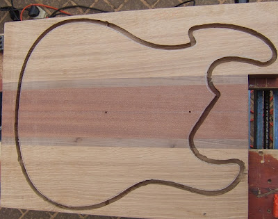
I managed to find some offcuts in a local timber supplier. A block of Sapele, a length of Black Walnut strip and a good chunk of Oak which had bounced on the planer and therefore had a defect area. All good low cost stuff. I cut and glued the wood to make a body-blank-sandwich. I made a Router-Planer from ideas on the Internet and trimmed it to 41mm

The first part was to draw a body shape. I used Paintshop to scale a PRS guitar body photo to real size using 150 pixels to an inch. I then used the distort tools to move the basic shape around and then used the curve draw tool to make new edges and lines. I could then print a portion of the overall design to A4 paper as full scale. By splitting the design into three sheets I could then print real-scale drawings taping together the sheets.  I included some red thin construction lines to aid alignment of the drawings. By the 8th design, iteration F it bore no resemblance to the PRS original and  I had a finished print which I glued down to 12mm thick MDF board. The MDF cuts well with a thin smooth cut Jig Saw blade and then I used a rasp (bottom of picture) and sandpaper to smooth the edges. Smooth lines here will pay dividends later and MDF is a lot softer than Oak.


The addition of drawn pickups and the neck cavity proved useful as well as the centre line being pre-printed. The final bridge will be a Les Paul type and not a Strat hardtail as in the original drawing.

The design was then transferred to the body blank and drawn on both sides. The blank had a centre line drawn on both sides. The distance from the base of the guitar from the edge ensured I was within a mm or so on both sides.


I then hand routed close to the edge with a 6mm dual cut router blade. This was SLOW work. You have to  go in 5-6mm depth steps but eventually you will remove wood and also end up at the depth limit of the cutter.


This is where accurately marking out on both sides with the template comes in. I then flipped the body over and began cutting again, though a bit further away from the line this time. As you can see below, I got daylight at last.


The template was then refitted and SCREWED to the top. This is where having the pickup marked acts as a sanity check when sticking a screw in. I started with a template cutter (bearing at the top) to cut an inch below the template. I then turned the body over and used a trim cutter (bearing at tip) to follow this cut and remove the rest of the material in a gentle manner.  As you can see below all the initial iterative cutting has left burn marks. For the final cut I removed the white tape and went with a full length cut trim cutter.


I have seen people using double sided tape to secure the template but I was glad I opted to use screws. I ended up moving the neck screw as I couldn't find a countersunk head screw and it got in the way of the router.


After the final cut very nearly all the burn marks were removed and the body had a good clean line and more importantly cleanly cut with no tear-out. Overall very pleased with progress so far.I'll update with more pictures as this progresses.


Sunday 15 April 2012

Ebay Refret with EVO Gold and filler


I got a Profile Silhouette Strat copy off ebay. I paid £115 for a made in Japan Stat, about 30 years old in good condition advertised with not much fret wear. However on receipt it was evident that it had spent a good deal of time playing rhythm on the first five frets as several areas were utterly shot. I decided to keep the guitar but attempt my first refret. After some research I stumbled across EVO gold fretwire. It's _marginally_ more expensive than standard nickel silver, but much more wear resistant and has a nice gold hue to the metal. 


On removing the frets I noticed exactly how deep the slots are compared to the fret tang and how much more the neck moved in my hands. The frets are obviously part of the structure and rigidity of the neck. That and  and I am now working old fret slots. It can't be good.  My solution was to use a resin wood filler to pack the slot prior the instant before fitting the fret. I placed electrical tape either side of the fret slot, filled the slot quickly and then pulled the tape. This leaves a clean surface and a well filled slot. The wood filler cures very quickly so it was one slot at a time. The excess appears out of the side of the slot so it doubles up as the slot filling job at the same time. The truss rod plays a lesser part now as the fretboard in more structural than before.  Six months later there are no issues. I am sure someone will have an problem with filling the slot but in this instance it seems to have worked a treat.


 As for the Jescar EVO gold fretwire, it works easily, polishes beautifully and string bending is all too easy. Someone please explain why EVO Gold isn't used on everything now and why I have to spend a fortune with Gibson before they will fit it. It costs about £2 more than nickel.... As for the Profile copy, with some decent pickups now installed you would never put it down for a Fender seven times the cost. Below, banging in the frets and taping up for the next swipe of plastic wood filler. I hope it shows the gold in the fret, and when polished it's like glass.


Added photo below as this is in natural sunlight which correctly shows the subtle gold. The dot markers were also changed on the guitar. The standard dots fitted were white plastic so I bought a pack of MOP (mother of pearl) the same size. Removal of the old dot markers was simple. You just stick a soldering iron into the middle and gently rotate it round. The plastic melts first and the glue soon follows allowing for a very clean removal of the old dot marker.


Wednesday 22 February 2012

Tag board vs PCB construction.

Whilst I have a deep loathing for voodoo electronics one conclusion I have arrived at is that tag-board construction will produce a different tone from the same design based on a PCB, and I believe that tag-board can prove best. So how did I arrive at this conclusion? 
I built a tag-board (not a turret board) based amp a while back with a fault. It was missing a wire that connected the preamp signal to the power output stage. So the amp was dead, right? Well no, it carried a very trebley signal at a low level to the speaker just because the components on the tag-board are forced to be so close together. This isn’t voodoo its called crosstalk and is well understood. I found the fault and the amp sprang to life. So it has a feed-forward path and a bit of treble gets added from somewhere to somewhere else, well so what.   
Well try an experiment, find a HiFi loudspeaker that has a Bi-wire option and play something familiar. Now disconnect the tweeter and have a listen, half the sound disappears and what is left is muddy and pretty torrid.  Lastly disconnect the woofer and connect just the tweeter.  It’s all treble as expected but the volume level compared with the woofer is fractional. Conclusion:- A small amount of treble carries the weight of the sound. Now back to the tag board where co-located components will cross-talk and bleed treble forward in the amp. I loaned the amp to a friend to check it out at volume, he concluded that it had an “air” …. and I think I know where it comes from.

Monday 30 January 2012

JCA20H with EL84 Triode / Pentode Switch and schematic circuit diagram.

Though the JCA20H is _only_ 20watts, you have to take account of how loud 20 watts is, how you define 20 watts (some define it at 1% THD, some at 5% THD, it makes a big difference) and how efficient your speaker is. I decided as it's a simple mod to put in a triode switch which simply drops the output power to about 10 watts. However I found that the triode mod has develops a much smoother tone which I like. A fly in the ointment is that I also unbalanced the phase splitter at the same time, so two variables at the same time. 
However looking at the spectrum for Pentode and Triode shows that the harmonic balance shifts and that the change in tone is not just perception and that switching a EL84 output stage between Pentode and Triode is not only an output power change. (unless the phase splitter modification has also contributed)

The initial test setup was to keep the input stage as clean as possible and then drive the output stage in pentode configuration to 5% THD into a 8ohm resistive load.

The normal Pentode spectrum (500Hz sine input) looked like this.

Pentode 5%THD into 8 ohm.

When switched to Triode mode the THD  increased by 1.2% and the upper spectrum changed structure.

Triode mode.

With the input gain set at maximum and clipping in the pre-amp you can see how the different operating modes modify the tone. In Pentode mode the dominant harmonic structure from the overdrive is clear.


In Triode mode again the upper harmonic structure produced from the preamp is modified.


 In the final version I fitted R7 and R5 (470R) as 1k5, 5 watt.  C-8 Helps keep the supply stiff, R-6 brings the phase splitter value from 82k to 50k which skews the output balance and allows the output stage to generate second harmonics (ongoing trial) C-6 reduces the power stage bandwidth to about 10kHz. The depth mod is from the web to boost low frequency.


JCA20H HSG output stage.
I did play with the idea of having SW1 as two separate switches so I could run one valve in pentode and one in triode in lieu of messing with the R46 value in the phase splitter but I didn't get around to it. You do loose some output power in changing the R46 value, but it is negligable.