Thursday 11 April 2013

ECC83 Valve with a low voltage 5V A/C heater (12AX7 Tube)

So why run an ECC83 / 12AX7 with a low heater voltage and what happens when you do?

I have a transformer from an old Linear Diatonic cage amplifier. How old? Well the 32uF+32uF can capacitor has May '58 as the date, but they didn't have just-in-time delivery in those days so I would put it at very early 60's best case. It was originally a two ECC83 + EL84 output with an EZ80 rectifier. It also had an auxiliary 6.3V and HT (B+) socket on the back, so I knew it had some capacity left over. It got put into a guitar amp and became three ECC83 + EL84 output +EZ81 rectifier. (I know, EZ81 is a 6.3V version of EZ80, but I had a new one and it worked OK.)

Now I want FOUR (new preamp + FX loop) ECC83 + EL84, but this may be pushing it a bit, and the last thing I want to do is slowly cook the transformer. If I lose the rectifier valve and go for a semiconductor bridge with a zener to drop the voltage back then I could possibly run the additional valve from the now unloaded 5V heater winding and reduce the total load on the transformer. The light heater loading of ~0.3A should allow the voltage to rise above 5V or safeguard from a low mains supply, but after looking on the net I could find very little in HARD figures. Most advice I saw was that this possibly won't work, with one reliable source saying yes it will be OK. (Valve Wizard)

The only way to decide was to go measure the configuration I was going to use. The measurement below used a DC lab supply for the heater. The voltage supply I have is limited to 210V so I couldn't test with a higher value. The valve was a JJ-Tesla ECC83S with about 50 hours on the clock. I would be looking at the 1-2-3 connected part of the triode. The other half was not connected and the heater was between pins 4 and 9 only. In test this would mean that the valve would be colder than if both heaters were working, but I think of it as margin.

 
Test Circuit. R3 is selectable as 120k or 240k
Firstly I did some DC testing to bottom out the heater. The heater cold resistance excluding wiring but including the socket was 6.156 Ohm. With a 6.3V supply and ignoring wiring this would draw 1.02A at switch on. In reality this would possibly be lower, but a good (6 Watt) kick to the guts none the less when turned on. When working at 6.3V the single heater draws 155mA equating to a hot resistance of 40.6 Ohm and a dissipation of 0.98 Watt. Working at 5V it drew 136mA  giving an effective hot resistance of 36.76 Ohm with a dissipation of 0.68 Watt which is 70% of the dissipation at 6.3V

With a 1V pk-pk test signal applied to the test circuit I got an output swing of 54.1V pk-pk with an anode resistance (R3) of 120k. With R3 = 240k the swing was 60.2V which is pretty much on the money.  Spice simulation came out as 55.16V  for 120K and 65.5V for 240K, so close enough.

Putting a 4V pk-pk input swing on the input it would drive the output into saturation. This should highlight any obvious weakness in using 5V. Firstly I looked at the negative side as this represents the largest current through the valve.

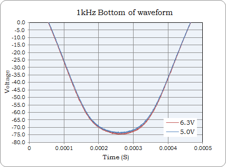
6.3V vs 5V. Input = 4V pk-pk input 210V supply voltage.

 There is no huge difference to be seen between either heater voltage, the 5V heater gain (blue) looks just shy. The top of the waveform should be well saturated so we will check that next.

As above....

The 5V heater is again a little shy of the 6.3V setting, but the behaviour entering and exiting saturation is pretty much the same. When lowering the input swing and operating in the available linear area the 5V gain is slightly lower but otherwise perfectly useable. Even at a 4V heater voltage the valve is still working in a healthy manner. With a 3V heater voltage the gain has dropped, but this is just experimental data.


So what conclusions does this present. For me and the new guitar amplifier, I'll happily put the first valve with both heaters on the 5V supply. Both stages are below maximum gain anyway. Some voices on the net did say I'll ruin the valve this way, but I found a table in an old design book which showed extended life extending to thousands of hours so I am happy with that.  I will also consider putting a series resistor in all the 6.3V supplied preamp valves from pin 9 to the centre pin of the base and then to the heater wiring. A 2.2 Ohm resistor should reduce the switch on current in the heater from 1 Amp to ~600mA whilst dropping the working voltage to ~5.68V (0.615V drop or ~82% of full heater dissipation) This should have virtually no effect. If it does, then 1 Ohm should be fine.

On the other side of the coin. I should possibly see if I can get a more representative voltage for the supply, 210V is sort of low.

EDIT / UPDATE 1

Below is with a 270V power supply with 6.3V and 5V heaters compared. This last test had both heaters wired in circuit. No change from previously observed measurements including at full saturation.

240K and 1.2V input. 73V pk-pk swing.

EDIT / UPDATE FINAL

I have an _OLD_ Mullard Ecc83/12AX7, silvering gone spotty really is shot. God knows how many hours. It still has some output but very non-linear. It normally sits on my desk as an ornament. In the 270V HT / B+ test it performed equaly badly with 6.3V and 5V heater voltages. The 6.3V specification seems to have a lot of margin built in. Just remember to include mains supply tollerance etc. when looking at your own transformer!


Friday 5 April 2013

DIY Front Panel in Acrylic / Plexi

New amp needs a new face. Looking around in the UK I can get a custom front panel made, but it seems a lot more costly than you can get say in the U.S. Some want .DXF as the file and not having Autocad or a package with this format blocks that route. What I could source very cheaply was some cut to size 1.5mm thick clear acrylic and a couple of sheets of water slide decal paper for a laser copier.

The acrylic was delivered promptly as four sheets cut to size and a set of panel graphics produced using Paint Shop Pro 9. The images were then all mirrored as the plan is to place them on the back of the acrylic and view them form the other side, ie the front. I can then paint over the transfer effectivly sealing them in. The paint observed from the front would have a perfect  finish no matter how lumpy it was put on, or that's the idea anyway. A few old CD cases proved that using finger daubed water acrylic paint.

The laser copier paper arrived with a warning about possibly melting onto the fuser roller of the copier which was not in the advert selling the paper (ebay). However the bigger the copier the more ECO friendly it is and the large business types therefore have a lower than normal working temperature. There was no issue with the printing and it gave razor sharp results. Unlike inkjet water decal paper it needs no lacquer overcoat which is why I chose it this time.

To make the panel it was first taped in place to the front of the chassis. Using an indelible marker the position of the controls was marked onto the back of the acrylic using the holes in the chassis as a guide.  On an earlier attempt I used a scribe which leaves a finer line, but the unevenness made ripples in the transfer on application.

Finished Item...Chuffed to bits!

Test acrylic taped in place and marked.

The transfers we cut out close and then placed in position. The best method I found was to use a white paper sheet under the acrylic with straight lines printed / drawn on. This way you have a datum for the bottom edge of the acrylic and the lines assist in ensuring that the top of the transfer where the wording is is straight.  It took a while to get the result right but here is what I found best.

Lined paper assists getting it straight.

Soak the transfer for thirty seconds and then place to one side for another. Line the acrylic up on the guide paper and place a bit of water where you want the transfer to go. Without this dab of water the positioning time is about twenty seconds. what can then happen is that part of the transfer can grab and when you attempt to move it the transfer will stretch or distort. The bit of water underneath gives you minutes of working time, however at this point it is prone to handling errors if you try to place another transfer as it is effectivly floating.

Using a ruler place as close as possible, note printed mirrored!

After positioning the transfer I would then flip the panel over. The transfer is now against the guide paper. It has enough friction with the guide paper that you can still finely position it if needed by moving the panel. When it is all correctly positioned simply apply pressure, the excess water will be pressed out and the transfer will adhere to the front enough to resist handling. The transfer can still be lifted with a knife edge if required. Having lined paper to do this part also helps but missing in the shot below.

Fliping over to check position and then press to affix.


With the transfers in place I painted the rear of the panel with several coats of artists acrylic paint. I could easily use a spray paint, but the acrylic allows me to test and wipe off. After several coats I did a final coat painted some paper and placed this as a protective backing.

Final coat and backing paper will form a protective seal.

The final result, well really please with this. The edges of the acrylic had some small chipping under the green protective film, but a quick sanding will remove these and they will sit behind the cabinet woodwork anyway.

With painting the transfer blends perfectly to the panel.


It worked out cheaper than having a custom panel, and I still have acrylic and transfers for the rear and a spare front.  One other point about the acrylic paint. It is not fully opaque to light. If I cut a small hole in the backing paper but not through the paint I could shine light  from behind which you would see as a bright yellow glow from the front.. I may not go for a panel mounted power light, but insted use a 3mm white LED mounted behing the panel to illuminate a small circle of blank panel adjacent to the power switch to indicate that the amp is on.

As a final note, If you are thinking if edge illuminating the panel then the transfer edge will become visible.

Wednesday 3 April 2013

Resistors, Carbon Comp vs Metal Film in Valve / Tube Amp Design.

As in previous post, I don't suffer snake oil etc in circuit design. _However_ whilst shopping for some parts I noticed I could also buy brown carbon composite resistors with nostalgic 3+1 coloured rings for 30 pence. Now they have lots of  know issues but I remembered reading years ago about voltage coefficient in my copy of Horowitz and Hill Sec.Ed.  The question I am looking at is could the voltage coefficient alter the sound of the amplifier? According to H/Hill above 250V the resistor changes value and at 1kV it is out by 29% (Chapter 6, pages 372/3). We are dealing with lower voltages, but across the anode resistor at clipping it could see ~250V potential, so I would like to check that area.

I happened to find an old carbon comp resistor, 680k value hidden away. With carbon composition this  is more of a pre-soldered guide than an absolute value. It was more like 688k.  I decided to do some DC tests to see how much, if any, it would change over a 210V range against a metal film of the same value.

Percentage change with applied voltage.

In the above plot there is a clear change in apparent resistance of the carbon resistor against an applied DC voltage. The measurement contradicts a H/Hill statement that it is really only above 250V where the voltage coefficient becomes apparent. Maybe they meant significant. To put this in prospective, of the original 688k value it represents a drop in resistance of over 20k. The metal film (red plot) is stable at 100.0%.

Having repeated the test and confirmed the behaviour I needed to know if this was something that takes seconds to change or is this change instantaneous and works in real time.

To check this I constructed a potential divider out of two resistors. The bottom resistor was a 62K metal film and the measurement was made across this device. The top resistor was the device under test being either the 688k carbon composition or a 680K metal film resistor. Using a linear ramp source to 210V I could measure the lower reference resistor and determine the behaviour of the top resistor. The tail off at high voltage is the probe capacitance, so linear to +170V.

Real Time Voltage vs Resistance change.

In the above plot the carbon (red) is plotted against the metal film (blue) with the left hand scale. You can see that the red line drops slightly more voltage at the 0.0001s (0.1ms) point as it has a slightly higher resistance value. However as the voltage rises it crosses the blue plot and ends up with a lower voltage drop. This is real time compression well within the audio range.  To clarify the difference in voltage drop is plotted in green on the right hand scale, -7V to +3V. This shows that at the 0.1ms point the carbon resistor is dropping about 1.3V more than the metal film as to be expected being a higher value resistor. However with ~180V applied at 0.48ms the carbon film resistor is now dropping 4.8V LESS. It has shrunk in real time.

Piecewise Linear and Poly Curve Fit.

In a final look at the data you can either view the drop in resistance as a three section piecewise linear (blue, orange & purple lines) with three gradients or curve fit to the equation shown in the title.

The real world effect for valve / tube amplifier designers is that the carbon composition resistor can add some non linearity and compression not normally present in metal film. In my opinion it would be a mistake to consider the use of carbon in the early stages of a cascaded design. When taking the first measurement at DC the digital display would flick around on the carbon resistor but was rock steady with the same value metal film. The noise is really something else. However as an anode resistor in the overdriven /clipping stage, well it may be worth the 30p to someone. I however will probably stick to metal film based on reliability. Is the above effect audible? I will have to say-

 possibly.