I have a transformer from an old Linear Diatonic cage amplifier. How old? Well the 32uF+32uF can capacitor has May '58 as the date, but they didn't have just-in-time delivery in those days so I would put it at very early 60's best case. It was originally a two ECC83 + EL84 output with an EZ80 rectifier. It also had an auxiliary 6.3V and HT (B+) socket on the back, so I knew it had some capacity left over. It got put into a guitar amp and became three ECC83 + EL84 output +EZ81 rectifier. (I know, EZ81 is a 6.3V version of EZ80, but I had a new one and it worked OK.)
Now I want FOUR (new preamp + FX loop) ECC83 + EL84, but this may be pushing it a bit, and the last thing I want to do is slowly cook the transformer. If I lose the rectifier valve and go for a semiconductor bridge with a zener to drop the voltage back then I could possibly run the additional valve from the now unloaded 5V heater winding and reduce the total load on the transformer. The light heater loading of ~0.3A should allow the voltage to rise above 5V or safeguard from a low mains supply, but after looking on the net I could find very little in HARD figures. Most advice I saw was that this possibly won't work, with one reliable source saying yes it will be OK. (Valve Wizard)
The only way to decide was to go measure the configuration I was going to use. The measurement below used a DC lab supply for the heater. The voltage supply I have is limited to 210V so I couldn't test with a higher value. The valve was a JJ-Tesla ECC83S with about 50 hours on the clock. I would be looking at the 1-2-3 connected part of the triode. The other half was not connected and the heater was between pins 4 and 9 only. In test this would mean that the valve would be colder than if both heaters were working, but I think of it as margin.
 | ||
| Test Circuit. R3 is selectable as 120k or 240k |
With a 1V pk-pk test signal applied to the test circuit I got an output swing of 54.1V pk-pk with an anode resistance (R3) of 120k. With R3 = 240k the swing was 60.2V which is pretty much on the money. Spice simulation came out as 55.16V for 120K and 65.5V for 240K, so close enough.
Putting a 4V pk-pk input swing on the input it would drive the output into saturation. This should highlight any obvious weakness in using 5V. Firstly I looked at the negative side as this represents the largest current through the valve.
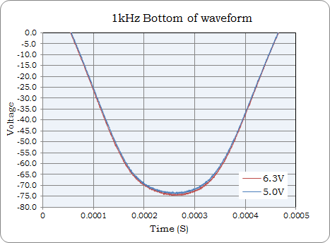 |
| 6.3V vs 5V. Input = 4V pk-pk input 210V supply voltage. |
There is no huge difference to be seen between either heater voltage, the 5V heater gain (blue) looks just shy. The top of the waveform should be well saturated so we will check that next.
 | |
| As above.... |
The 5V heater is again a little shy of the 6.3V setting, but the behaviour entering and exiting saturation is pretty much the same. When lowering the input swing and operating in the available linear area the 5V gain is slightly lower but otherwise perfectly useable. Even at a 4V heater voltage the valve is still working in a healthy manner. With a 3V heater voltage the gain has dropped, but this is just experimental data.

So what conclusions does this present. For me and the new guitar amplifier, I'll happily put the first valve with both heaters on the 5V supply. Both stages are below maximum gain anyway. Some voices on the net did say I'll ruin the valve this way, but I found a table in an old design book which showed extended life extending to thousands of hours so I am happy with that. I will also consider putting a series resistor in all the 6.3V supplied preamp valves from pin 9 to the centre pin of the base and then to the heater wiring. A 2.2 Ohm resistor should reduce the switch on current in the heater from 1 Amp to ~600mA whilst dropping the working voltage to ~5.68V (0.615V drop or ~82% of full heater dissipation) This should have virtually no effect. If it does, then 1 Ohm should be fine.
On the other side of the coin. I should possibly see if I can get a more representative voltage for the supply, 210V is sort of low.
EDIT / UPDATE 1
Below is with a 270V power supply with 6.3V and 5V heaters compared. This last test had both heaters wired in circuit. No change from previously observed measurements including at full saturation.
 |
| 240K and 1.2V input. 73V pk-pk swing. |
EDIT / UPDATE FINAL
I have an _OLD_ Mullard Ecc83/12AX7, silvering gone spotty really is shot. God knows how many hours. It still has some output but very non-linear. It normally sits on my desk as an ornament. In the 270V HT / B+ test it performed equaly badly with 6.3V and 5V heater voltages. The 6.3V specification seems to have a lot of margin built in. Just remember to include mains supply tollerance etc. when looking at your own transformer!
This comment has been removed by the author.
ReplyDeleteHi Roosville. I appreciate and have benefited from your blog in a number of ways. Thank you very much.
ReplyDeleteI have a comment on the heater voltage question. I run my valve heater at half power or less quite often. I have a heavily-modded JCA20H, and the amp entire will run at half voltage or less. I looked into the problem of cathode stripping, and could find very little hard information, but the problems seem to be associated with high-heat/high-power* (particularly spikes). Low heat/high power appeared to cause a bit more wear, as did high heat/low power, but low power/low heat seemed to be fine. (*Of course a high enough power level or spike will fry any tube; the values were not specified; I do not think any long-term bench-test info is available, though I am sure someone must have done this work.)
The answers I got made me question the wisdom of running 12AX7s at their rated heater (and plate!) voltages, at least in guitar amplification (isn't squishing the positive side of the wave what we _want_?). Also it seems that heater voltages were designed for highly efficient functionality and low distortion at the expense of tube life.
Since the rated heater voltages were specified from the original tube manufacturer, I would not be surprised if the heater voltages were specified "warm" on purpose, both to make up for inadequate power supplies in some areas (for low distortion) and to cause excess tube wear to increase profits - but not _hot_, so the replacement figures were acceptably low to their customers, and for areas (like yours) where the line voltage is higher than normal (an 12AX7/ECC83 being a consumer audio tube made by RCA, rather than, say, a military RF valve pressed into audio application).
It seems that many if not most guitar amp designers are stuck in a rut. Thanks for publishing.
[PART ONE]
ReplyDeleteSince publishing my first response, I have done some work with half-wave rectification and Zener-dropping AC heaters; the results were quite interesting. Also I would like to retract the remarks on cathode stripping, which does not pertain to amplifier tubes (as opposed to cathode poisoning, which does and which apparently is the source of some problems with standby switching).
I would like to relate some of my experiences regarding the implementation of these mods and the tonal results, particularly the mods pertaining to the Valve Wizard B+ trickle/heater power-dropper standby switching solution ( http://www.valvewizard.co.uk/standby.html ).
The trickle switch is a replacement standby switch which, rather than removing all B+ voltage, simply reduces it to a level at which no amplification takes place (there is a very slight hiss from the speaker cab, but no signal is passed - I used a 220K, 100-volt carbon composition resistor I had handy, resulting in a B+ voltage at standby of 25 volts). [In addition, the low-but-not-zero voltage at startup prevents some problems which can shorten tube life. I won't go into them (and I'm sure you (Roosville) are quite familiar with them. For those readers who don't, and are interested, the Valve Wizard site is an excellent technical reference source, as Roosville has pointed out more than once.]
The modded standby (trickle) switch does not need _both_ B+ lines, just the "hot" lead, so the other side of the switch is open, and can be used as a switch for a dropping resistor, or -if it is an AC heater- a rectifier, for the valve heaters.
I elected to use a 1000-volt Zener rectifier diode on one half of the heater line, between the switch contacts. The results were less than satisfactory, as startup time was lengthened considerably (because the tubes were too cold to conduct with the heater at half voltage (interestingly, once warm, the heater voltage can be half-wave rectified and the amp will still work, though the tone is markedly different - more on this later)). Accordingly, I installed a heater-dropper-cutout switch, which allows for a "hot start", and also for the heater to be given an extra period to warm up when leaving standby/trickle mode, simply by flipping the dropper-defeater switch (I call it an "ignition switch") a few seconds before the standby/trickle switch.
[PART TWO]
DeleteIt may seem obtuse, doing all that rewiring... to add an extra switch to defeat the rest of the rewiring (if selectively), but the extra tube life provided by the lower valve temperature, and the elimination of cathode poisoning (which is caused by running the heater without voltage on the valve, if I understand what I have read on the subject), plus the ability to have a quick startup time, I find quite worthwhile. The "ignition switch" may be of any convenient size, as well, though I elected to use one the same size as my power and standby switches, arranged so I can flip them up in a 1-2-3 pattern to start up the amp (ignition on, "power" on, standby up (B+ power on), just for convenience and simplicity).
What I really wanted to comment upon is the tonal effects of running the heater voltage low as opposed to dropping the voltage to the amp entire using a variable AC transformer ("Variac"): when running my JCA20 at very low voltages a distinctive "woolly", "fuzzed-out" tone develops. This would seem to be due to the effects of extreme power tube distortion due to running the tubes in a very nonlinear region of operation; however, I have achieved very close to the same tonal range by simply half-wave rectifying the heater. It would seem that a significant element of the "brown sound" involves (what most would consider) "insufficient" heater voltages (of course the necessary voltage depends upon what the circuit is required to _do_, so "sufficient voltage" is variable, and an opinion, besides).
My next experiments along this line have to do with having separate, adjustable heater and B+ power line voltages (as in London Power's variable B+ solution/s, or a VVR (though I would prefer to find a solution using simple components like pots, rheostats, or thermistors, rather than ICs and the like... though I am okay with diode rectification (of the DC power sections; I'm not speaking of the unspeakable practice of diode clipping in supposedly "all-tube" amps - that's a separate concern entirely!), so I'm not an incurable purist)). This (running separate, gradated voltage-reducing controls) would allow me to evaluate, separately and together, the elements of the Variac-dropped "brown sound", and to elucidate to what extent the tone is due to running the tube in a nonlinear region, and how much is due to the heater being unable to "properly" conduct (or conducting less efficiently, as in your graphs above).
Excellent written reply Felix! Very interesting.
DeleteThanks for the blog loaded with so many information. Stopping by your blog helped me to get what I was looking for. http://anixusa.com/
ReplyDelete